 |
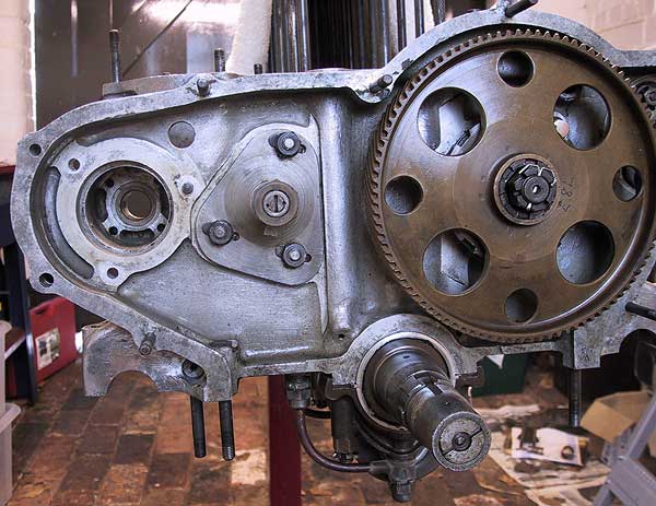
The idler gear spindle and bracket re-attached. The mating face around the oil feed hole was sealed with a gasket compound. |
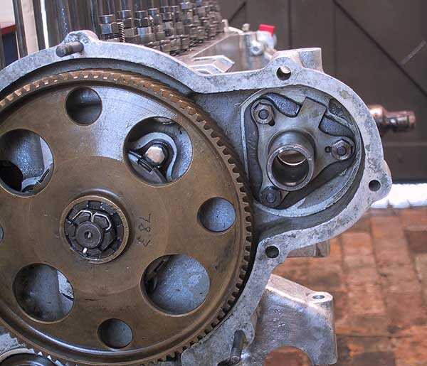 |
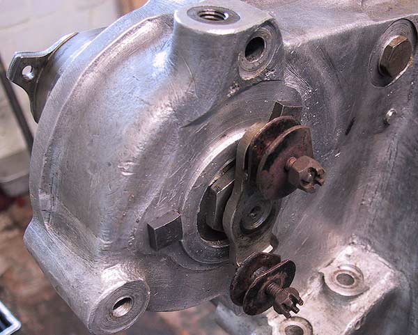
The outer spindle for the dynamo drive installed and the nuts held with tab washers. |
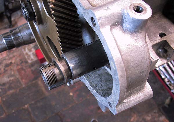 |
The inner tube that supports the pinion bearing is installed from the back of the casting. Shown here is the spacer that prevents the gear teeth fouling the back of the casting and ensure accurate meshing with the camwheel. |
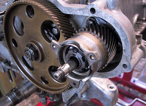 |
Pinion and bearing installed, serrated nut tightened and held in place by a lock tab washer. Note the bearing retaining plate attached to the front of the pinion body. The drive shaft is resting in the inner tube awaiting final assembly. The drive plate is located using 6 square splines in front of a taper instead of the usual Woodruff key. |
 |
Rear view of the dynamo drive shaft. |
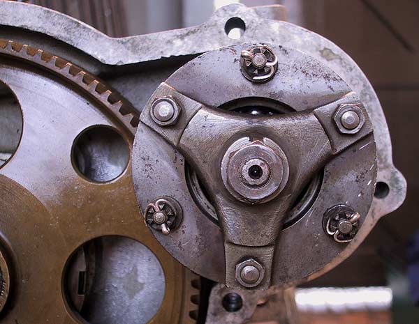 |
The spring driving disk hold the drive shaft so that it does not touch the walls the the tube through which it passes. This complicated drive arrangement compensates for any misalignment between the axis of the pinion and dynamo. |