 |
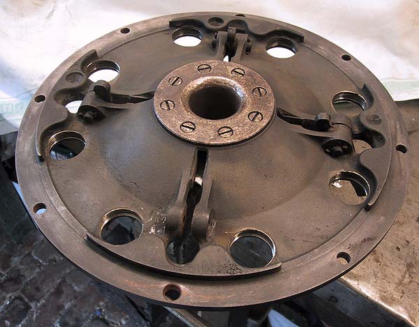
Inside the clutch pressure plate. The spring housings have been
removed and the toggle levers are being removed. |
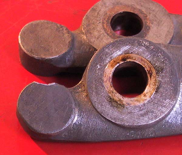 |
A close-up shot of the wearing end of a toggle - old one at the front
and replacement behind. |
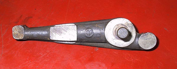 |
The replacement levers came from a slightly earlier engine. This
shot shows the replacement lever lying on top of the original.
It must be assumed that the earlier design needed beefing up. |
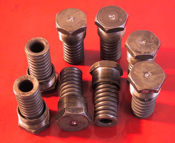 |
All 8 clutch springs replaced and re-assembled. Each assembly
is stamped with its position in the pressure plate, which is also stamped. |
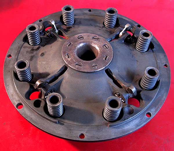 |
Inside the pressure plate showing the replacement toggle levers and
new springs. |
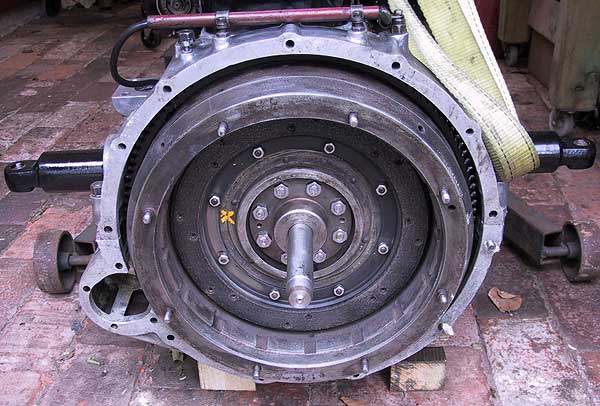 |
The existing friction lining re-attached to the flywheel. The
back plate and flywheel are both stamped '0' to ensure correct alignment.
A mandrel was fabricated to align the clutch driven plate. The
mandrel diameter is 1" with the front section reduced by 0.016"
to fit inside the spigot bearing.
|
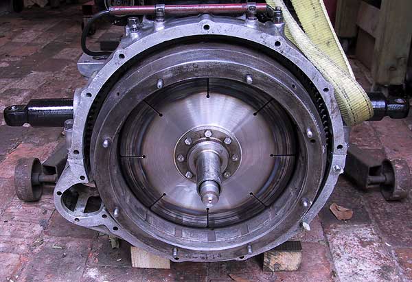 |
Driven plate in position. |
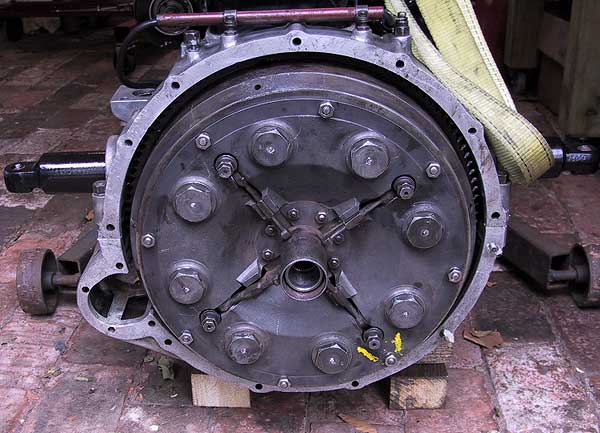 |
The pressure plate is first attached with the spring housings unscrewed.
The plate is stamped to ensure correct alignment on the flywheel.
Additionally, there are two studs with oversized shanks.
The perimeter nuts are tightened first followed by the spring housings.
|
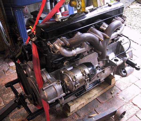 |
Inlet and exhaust manifolds fitted using new gaskets throughout. |